ESPtoy Documentation
(Version: 26 Feb 2018)
Copyright 2018 Burney Waring
Copyright 2018 Burney Waring
Installing ESPtoy
Basics of ESPtoy
ESPtoy Details
ESPtoy Cases
ESPtoy Construction
ESPtoy License
Contact Burney Waring
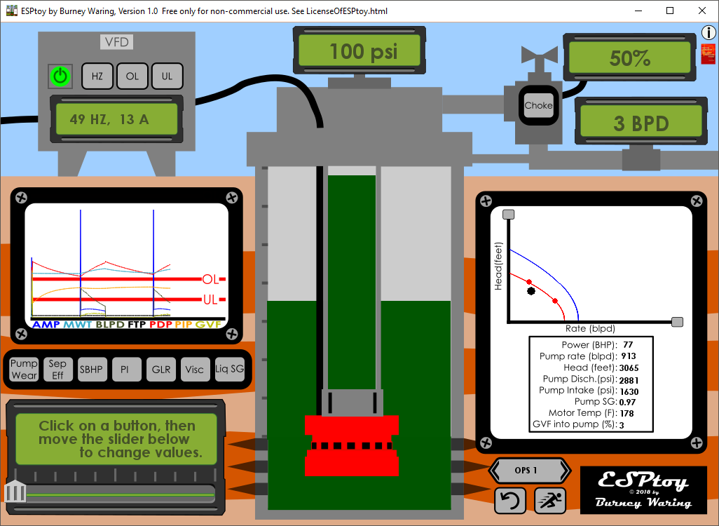
Details of the ESPtoy Interface
It is more fun just to click around to see what you can find. However, just for reference:HZ is the frequency of the VFD. This controls the speed of the pump. Head increases with at the square of the speed, power at the cube of the speed. (See Affinity Laws)
OL and UL are overload and underload trip values. Current that goes over or under these values will cause the power to the pump to trip off. This is to protect the system from burning up the motor or damage to the pump, for example if gas is drawn into the pump when the casing level gets too low.
Pump Wear is an adjustment to explain how a pump has degraded from the original performance. In ESPtoy it is represented as a diameter change ratio:
worn diameter/original diameter. So, And pump wear affects rate by proportionally to:
(worn diameter)/(original diameter).
And pump wear affects head by:
((worn diameter)/(original diameter))^2.
Pump Wear is a sort of 'fudge factor'. The reason the pump is not at the correct rate could be due to actual abrasion of the pump rotors (sand, proppant flowback) so that the diameter is worn, but also due to scaling, mechanical problems in the pump, seals, motor, etc., viscous fluids, or any of several incorrect values used in analysis of pump performance. However, Pump Wear is a very good value to use for surveillance of ESPs. If Pump Wear suddenly or gradually increases, it may be an indication that preventative maintenance may be beneficial, or even that you should start planning a pump replacement.
Sep Eff is Separator Efficiency. This is the gas separation that occurs prior to the pump intake. Gas is generally bad to have in a pump because it takes up the space for liquid that you would rather be pumping. The higher the Sep Eff value, the lower the Gas Volume Fraction that enters the pump.
Unless the intake pressures are relatively high, GVF into the pump probably should not exceed about 10-15%. Gas into the pump can cause 'gas locking' where the gas in the pump is of too low a density to generate sufficient pressure relative to the fluid column reaching the surface. Without sufficient liquids movement, the motor and pump may rapidly fail. Too much gas entering the pump may have similar detrimental effects as cavitation.
A standard pump intake is really just a screen to keep the rocks out and will separate little or no gas away from the pump. If the casing is large, or the pump is mounted eccentrically, these may help give a bit of benefit.
A reverse flow separator my increase separation efficiency to about 20%.
If the GVF exceeds 20%, then you should use a rotary gas separator, driven by the pump/motor shaft. Rotary gas separators may require a bit more horsepower (<5%), and this is not included in ESPtoy. These can achieve 40-80% separation efficiency. They can be mounted in series to achieve 50-90% separation efficiency.
For applications where the gas into the pump is still too high, a Gas Handler can be used, which uses large axial impellers to scoop up gassy liquids and push them into the pump.
Since the motor needs cooling with mass flow past the motor housing, more gas will cause the motor to run hotter. This is not improved by the gas separator efficiency.
SBHP is the well's Static Bottom Hole Pressure. In ESPtoy, the pump is placed at the 'bottom hole'. The well perforations or reservoir datum might be higher or lower, but in ESPtoy the SBHP has the datum at the pump depth. The Pump Intake Pressure and Pump Discharge Pressure also use the pump depth as their datum. For your reference, this depth is 7000 feet.
Watch what happens to the casing fluid levels when you increase SBHP. The casing level is directly impacted by the SBHP when the well is not pumping.
PI is the Productivity Index of the well. This determines the production for a given Flowing Bottomhole Pressure. In ESPtoy FBHP is the same as Pump Intake Pressure. Production is given as PI x (SBHP - FBHP) and is in Barrels of Liquid Per Day (blpd). The higher the PI of the well, the less work the pump has to do for a given production rate.
GLR is the Gas to Liquid Ratio of the production. The higher the GLR the more gas is produced for a given amount of liquid production. A higher GLR will give a higher Gas Volume Fraction (GVF) into the pump.
Visc is viscosity of the produced liquid. A higher viscosity will reduce the head and rate the pump can create, and will also reduce its efficiency so that it would require more power to produce a given rate and head. I obtained these factors from the Centrilift book, listed at the bottom of this document.
Liq SG is the liquid specific gravity of the liquid into the pump.
Power (BHP) is measured in horsepower (HP). The horsepower required by a centrifugal pump is:
HP = BPD x feet of head x SG / (136000 x pump efficiency).
BHP is Brake Horse Power, as shown in ESPtoy, is the power that is required by the motor to supply the pump for a given liquid rate and head.
BHP = HP / Power Factor / motor efficiency + losses in cables, etc.
A (Amps) is the current required for this power is:
Amps = BHP * 746 / 1.73 / Volts.
ESPtoy assumes a fixed 2500 volts in its calculations. High voltage is required to be able to get sufficient power to the motor through 7000 feet of cable without too much power loss. Plus, lower voltage would require higher amperage and thus larger conductor cables that would be hard to fit into the well casing along with the pump.
Pump rate is the liquid rate in barrels per day. In ESPtoy, I have assumed that the liquid is the same volume at the pump as at the meter. In reality oil volume would shrink 20% or so. To keep the inputs to a minimum, ESPtoy does not include a water cut (%) and instead assumes a Liquid Specific Gravity that could be made up of any mix of oils and water with varying densities.
Head can be thought of as the distance fluids are lifted to the surface. It can also be thought of as a measure of effort that remains the same no matter the density (SG) of the fluid.
Head = 2.309 x psi / SG, where psi is the difference between two pressures.
To get fluid out of the well, the pump must supply the difference in the tubing fluid level and the casing fluid level plus any difference in pressures. Note that in the ESPtoy well, the casing is tied into the flowline downstream of the Choke to allow gas to flow along with the liquid. So, the head should be zero if there is no chokinh and the fluid levels are the same. Try turning off the pump and watch the head go to zero.
Pump Disch is the Pump Discharge Pressure, the pressure at the outlet of the pump.
Pump Intake Pressure is the pressure at the intake of the pump, which in ESPtoy is the same as the flowing bottomhole pressure, FBHP.
Pump SG is the specific gravity of the fluid going through the pump, the density as a ratio to water.
Motor Temp is the motor winding temperature. The temperature is the static temperature of the well fluids at the pump (163 F), plus the temperature rise caused by the inefficiency of the motor and other losses that turn to heat, minus the heat that is removed by fluid moving past the motor. The temperature rise can be estimated by calculating the fluid temperature after it has passed the motor:
temp rise to fluid = (HPlosses x 42.44) / ((mass of fluid passing the motor in lbs / minute) x specific heat of the fluid in BTU/lb-F)
Then, add the the internal temperature rise cause by loading:
temp rise inside motor = temperature rise at full horsepower*(HPactual/HPdesign)^1.2
Gas has a low specific heat and a low mass compared to water, so I have assumed that the temperature rise is reduced proportionally with GVF. A motor with only gas around it will overheat. A normal ESP motor has a maximum operating temperature, but the fluid that passes the motor will carry the heat to the pump and cable also. So the system may have an even lower maximum operating temperature. Beware high GVF. Remember that gas separator efficiency does not help the motor temperature. And lower SG liquids have lower specific heats and therefore cause higher motor temperatures.
GVF is gas volume fraction, the fraction of the total volume of fluids going through the pump. The amount of gas is related to GLR which would be the gas separated from the liquid at atmospheric pressure, leaving behind the dead liquid. However, only a fraction of the total gas will come out of solution at the pump intake (much more will come out on the way to the surface, as the pressure decreases).
Gas rate in BPD at downhole conditions, coming out of solution, minus the gas through the gas separator:
G = (GLR in reservoir - GLR at pump intake) x BLPD / 5.61 x (35.37 x p/ (ZT)) x (1 - sep eff)
GVF = G / (G + BLPD)
In ESPtoy I have (over)simplified this by not calculating the oil rate and water rates at downhole conditions, and substituting 14.7/Pump Intake Pressure for the downhole volume correction, and assuming that the gas coming out of solution at the pump is GLR x (1 - FBHP/SBHP).
The Choke applies a back pressure on the well, depending on the choke size and the rate of production. A smaller choke setting causes a higher flowing tubing pressure (FTP) which will increase the head on the pump. This may help move the pump out of an Upthrust condition.
Upthrust is the condition where the pump impellors are swept up against their housings. This can shorten the runlife of an ESP pump. This occurs with relatively low heads and high rates.
Downthrust is the condition where the pump impellors are pushed down against their wear surfaces. A bit of downthrust is expected. Too much downthrust may fail the pump. This occurs at relatively high heads and low rates.
Note: We often discuss upthrust and downthrust regions as starting exactly where the dots are on the pump curve. However, in reality we don't know exactly where they are. The range given is the efficient range. The further outside you go, the more inefficient and the more likely that you encounter some mechanical problems. It wouldn't worry me to operate right on the upthrust point, or even temporarily at a higher rate. Engineers who choose and size ESPs in fact aim for that end of the curve, because as wells deplete the operating point moves left (lower rates and more head required). An operator can also choke the well to move the operating point to the left, but not to the right.
Catalog Head and Catalog Rate for the pump can be changed in ESPtoy. This is essentially choosing a different ESP for the well. This can be done by clicking on the very small gray squares at the ends of the axes in the pump curve graph to be able to make these changes.